High Voltage Solutions
XRM / XRF Series
Ac-Input Modular High Voltage Power Supplies
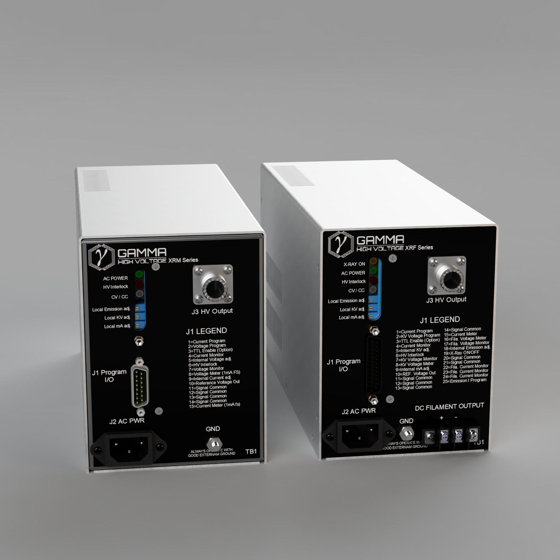
Compact AC-input supplies for regulated high voltage and low-power X-ray systems. XRM provides voltage and current control; XRF adds emission and filament controls for integrated X-ray tube operation.
Key capabilities
- Local or remote voltage and current control
- Constant-voltage / constant-current regulation
- Voltage and current monitoring
- External interlock and arc/short protection
- XRF emission, filament, and X-ray enable controls
Typical applications
- X-ray systems
- CRT and projection systems
- Photomultiplier bias
- Capacitor charging
- Integrated low-power X-ray tube control
Standard model guide
| Model | Output voltage | 60 W current | 100 W current |
|---|---|---|---|
| XRM 1.5 | 0-1.5 kV | 40 mA | 66 mA |
| XRM 3 | 0-3 kV | 20 mA | 33 mA |
| XRM 5 | 0-5 kV | 12 mA | 20 mA |
| XRM 10 | 0-10 kV | 6 mA | 10 mA |
| XRM 15 | 0-15 kV | 4 mA | 6.6 mA |
| XRM 20 | 0-20 kV | 3 mA | 5 mA |
| XRM 30 / XRF30 | 0-30 kV | 2 mA | 3.3 mA |
| XRM 40 / XRF40 | 0-40 kV | 1.5 mA | 2.5 mA |
| XRM 50 / XRF50 | 0-50 kV | 1.2 mA | 2 mA |
| XRM 60 / XRF60 | 0-60 kV | 1 mA | 1.67 mA |
Select XRM for general regulated high voltage or XRF for integrated X-ray tube operation. Choose the output voltage and 60 W or 100 W power class; add P or N to XRM model numbers for polarity. Contact Gamma with XRF tube voltage, current, and filament requirements.
Specifications
Electrical characteristics
Mechanical and interface
Configuration and options
Integration
- 0-10 V local or remote kV programming
- 0-10 V local or remote current programming
- XRM voltage/current monitors and HV interlock
- XRF adds emission and filament programming/monitoring
- XRF includes X-ray ON/OFF and optional TTL enable
- Factory-set kV ramp available on XRF
Available options
- Positive or negative XRM polarity; add P or N suffix
- 195-245 VAC or 24 VDC input versions
- TTL-compatible enable
- Customer-specified high voltage connector
- XRF filament voltage and current selected for the tube
- Factory-set XRF high voltage ramp
- RoHS-compliant version available
- Higher-voltage and custom configurations available
Control interfaces
XRM models use a 15-pin J1 control connector. XRF models use a 25-pin J1 connector with additional emission and filament functions.
XRM J1 - 15-pin
| Pin | Function |
|---|---|
| 1 | Current program |
| 2 | Voltage program |
| 3 | TTL enable - option |
| 4 | Current monitor |
| 5 | Internal voltage control |
| 6 | High voltage interlock |
| 7 | Voltage monitor |
| 8 | Voltage meter - 1 mA full scale |
| 9 | Internal current control |
| 10 | Reference voltage |
| 11-14 | Signal common |
| 15 | Current meter - 1 mA full scale |
XRF J1 - 25-pin
| Pin | Function |
|---|---|
| 1 | Current program |
| 2 | Voltage program |
| 3 | TTL enable - option |
| 4 | Current monitor |
| 5 | Internal voltage control |
| 6 | High voltage interlock |
| 7 | Voltage monitor |
| 8 | Voltage meter - 1 mA full scale |
| 9 | Internal current control |
| 10 | Reference voltage output |
| 11-14 | Signal common |
| 15 | Current meter - 1 mA full scale |
| 16 | Filament voltage meter |
| 17 | Filament voltage monitor |
| 18 | Internal emission adjustment |
| 19 | X-ray ON/OFF |
| 20-21 | Signal common |
| 22 | Filament current monitor |
| 23 | Filament current meter |
| 24 | Filament current program |
| 25 | Emission-current program |
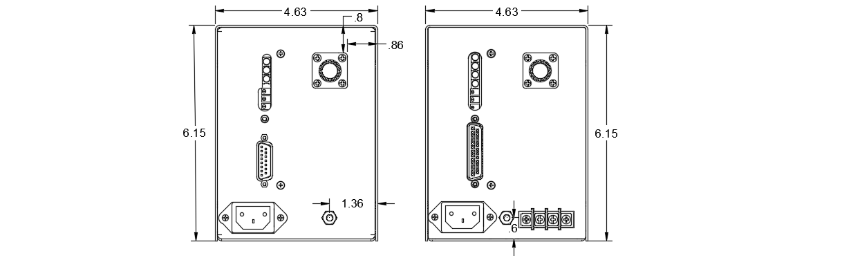
Mechanical drawings
Dimensions are in inches unless otherwise noted. Contact Gamma to confirm the final enclosure and connector arrangement for your configuration.

XRM / XRF Series resources
Download the data sheet or contact Gamma for configuration assistance.