High Voltage Solutions
MCR Series
Miniature Regulated High Voltage Converters
Miniature regulated 24 VDC-input high voltage converters for low-current instrumentation. A 0-10 V program input provides proportional output control, while a floating output supports fixed positive or negative polarity. PCB-mount and connectorized configurations accommodate multiple integration environments.
Key capabilities
- Compact aluminum construction
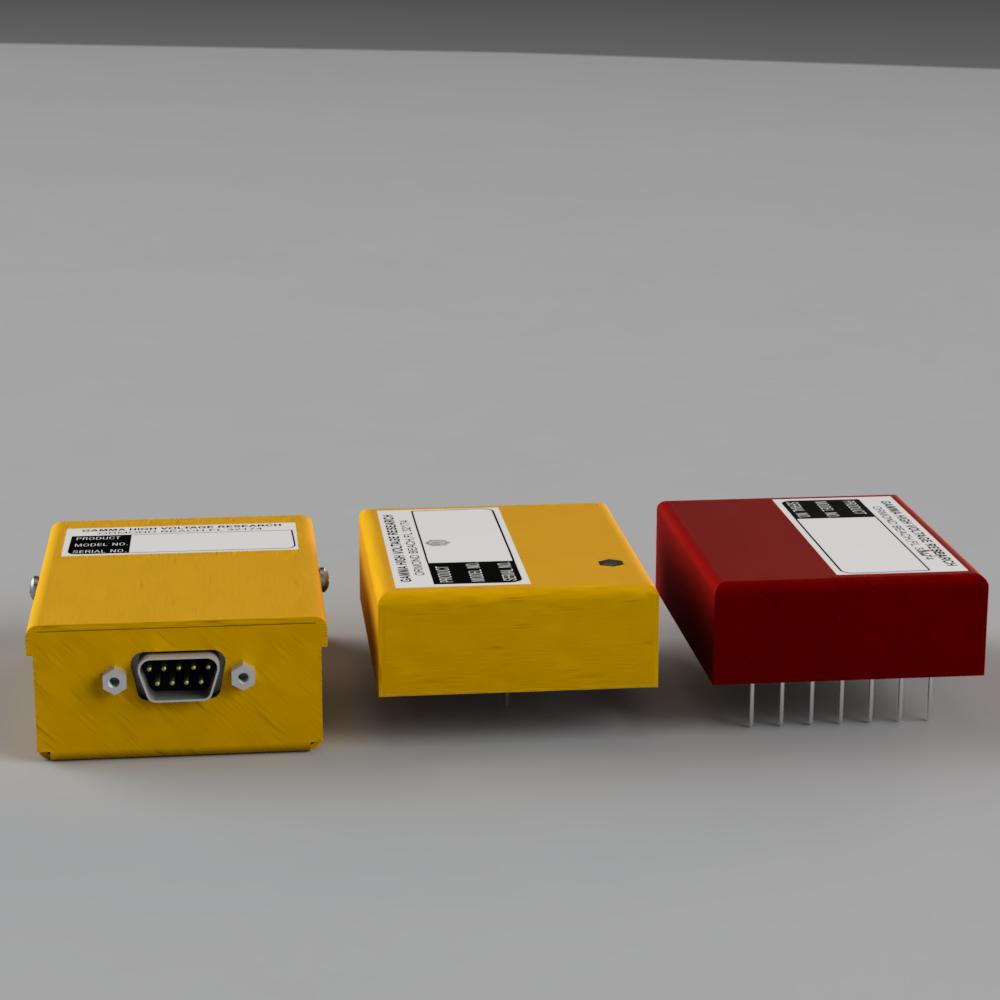
- PCB-mount and connectorized configurations
- 0.001% maximum ripple
- Positive or negative fixed-polarity output
- Internal +10 V reference
- Arc-over and short-circuit protection
Typical applications
- Photomultiplier tubes
- Solid-state detectors
- Analytical instrumentation
- Spectral source lamps
- Inkjet printing and gas chromatography
Standard model guide
| Model | Output voltage | Output current |
|---|---|---|
| MCR-0.3 | 0-300 V | 0-5 mA |
| MCR-0.6 | 0-600 V | 0-2.5 mA |
| MCR-1.0 | 0-1,000 V | 0-2 mA |
| MCR-1.5 | 0-1,500 V | 0-1.25 mA |
| MCR-2.0 | 0-2,000 V | 0-1 mA |
| MCR-2.5 | 0-2,500 V | 0-0.75 mA |
| MCR-3.0 | 0-3,000 V | 0-0.5 mA |
| MCR-5.0 | 0-5,000 V | 0-0.25 mA |
Choose the model for the required output voltage and append P or N to identify fixed output polarity. Contact Gamma to select the appropriate mounting and connection arrangement.
Specifications
Electrical characteristics
Mechanical and interface
Configuration and options
Integration
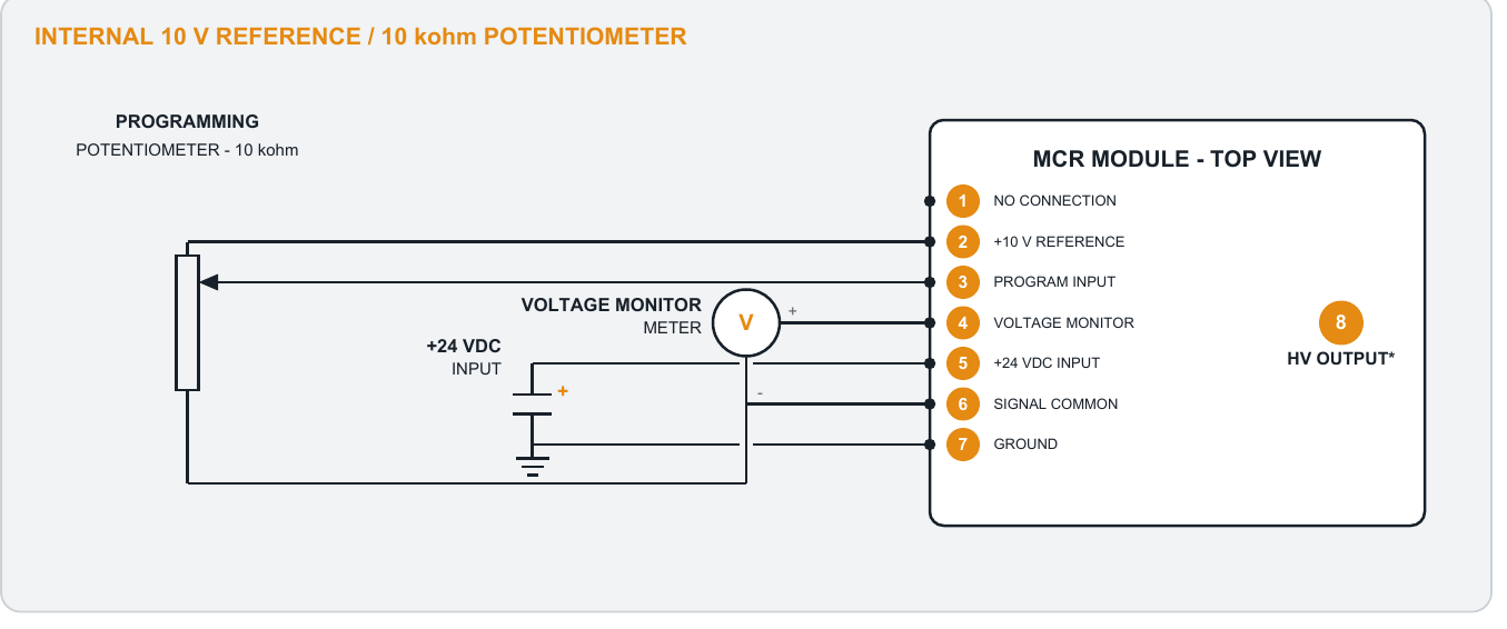
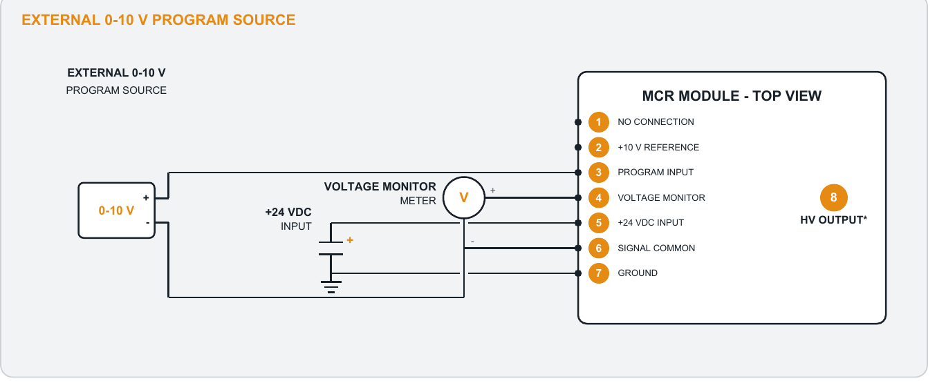
- Pin 1: no connection
- Pin 2: +10 V reference
- Pin 3: control-voltage input
- Pin 4: output-voltage monitor
- Pin 5: +24 VDC power input
- Pin 6: signal common; pin 7: ground
- Pin 8: high voltage output through 3 kV; ground above 3 kV
Available options
- Program with a 10 kΩ potentiometer using the internal reference
- Program with an external 0-10 V source
- Monitor output with a ground-referenced 0-10 V signal
- Connectorized and custom mechanical configurations available
- Custom electrical variants available
- RoHS-compliant version available
How to order
Programming interface
The finalized data-sheet diagrams are reproduced below for direct reference.
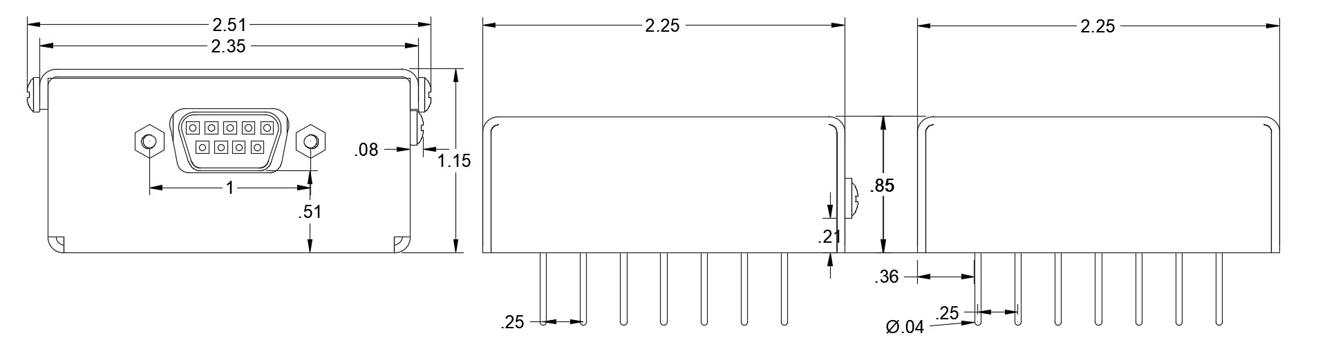
Mechanical drawings
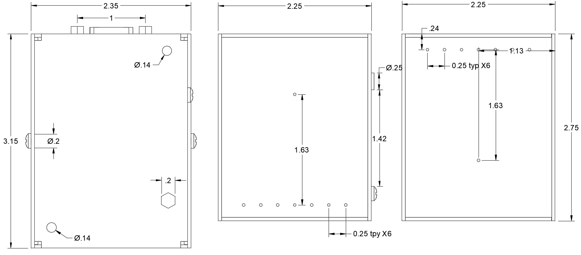
Dimensions are in inches unless otherwise noted. Contact Gamma to confirm the final enclosure and connector arrangement for your configuration.
MCR Series resources
Download the data sheet or contact Gamma for configuration assistance.